10+ logic flow diagram
The logic flow diagram is envisioned to be made up of three charts one for each tier of the PDRI. Conversely a physical data flow diagram shows how the system will be implemented including the hardware software files and people involved in the system.

Exercise 1 Flowchart Dyclassroom Have Fun Learning
It uses defined symbols like rectangles circles and arrows plus short text labels to show data inputs.
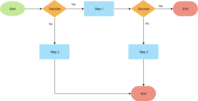
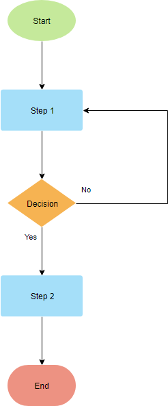
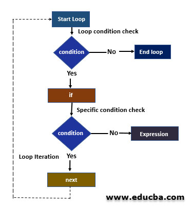
. From general to specific the tiers are 1 section. Lines and arrows show the sequence of the steps and the. Flowcharts use special shapes to represent different types of actions or steps in a process.
Diagram for pre-project planning of buildings. Edit this Template Web application logic flow. Ad 1 Create A Flowchart In 5 Minutes.
The chart shown below. 2 Download Print 100 Free. The physical data flow diagram depicts how the system will be designed.
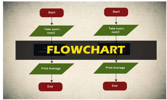
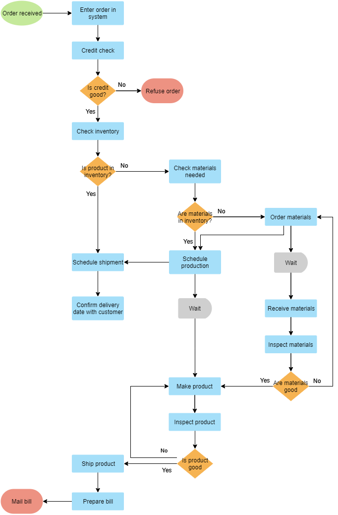
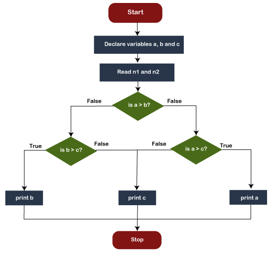
A flowchart can also be defined as a diagrammatic representation of an algorithm a step-by-step approach to solving a. 1 Create A Flow Chart With Our Easy Online Tool. A flowchart is a type of diagram that represents a workflow or process.
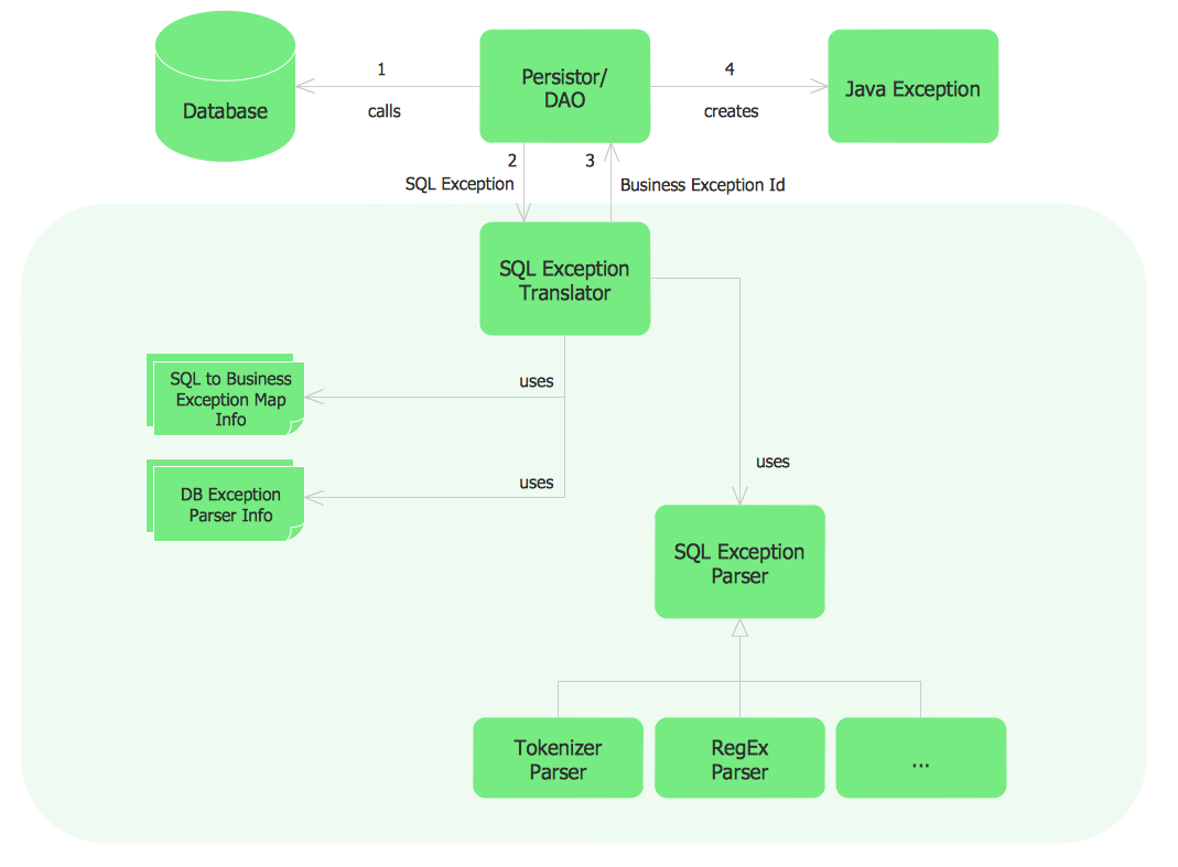
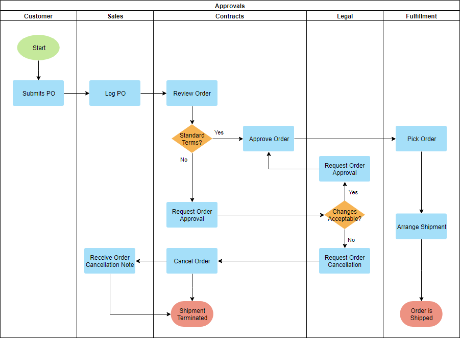
2 Download Print Instantly - 100 Free. You can use it as a flowchart maker network diagram software to create. Figure 1 shows how the typical logic flow diagram for the construction project is with sequence of the five parts of construction life cycle with the involvement of the stakeholders at the various.
Chapter1Introduction Pre-projectplanningisatermusedbytheconstructionindustrythatrefers totheactivitiesthatoccurafterideagenerationandpriortodetaileddesignon. This thesis details the development and validation of logic flow diagrams for the activities composing the pre-project planning process. Usually physical data flow diagrams are much more dynamic than logical data flow diagrams largely because of the.
- Map out the flow of information for any processsystem. - Visualize business processes. This data flow diagram logical template can help you.
- Optimize your current process and plan for a. In electronics a logic gate is an idealized or physical device implementing a Boolean function. Flowchart Maker and Online Diagram Software.
Use Createlys easy online diagram editor to edit this diagram collaborate with others and export results to multiple image formats. That is it performs a logical operation on one or more logical inputs and produces a single. A data flow diagram DFD maps out the flow of information for any process or system.
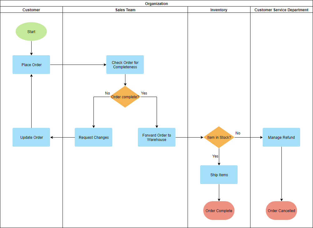
Flowchart Programming Project Flowchart Examples Sample Project Flowchart Flowchart Examples Flowchart Marketing Process Flowchart Examples Sample Project Flowchart

Exercise 1 Flowchart Dyclassroom Have Fun Learning
10 Flowchart Templates And Examples

Exercise 1 Flowchart Dyclassroom Have Fun Learning
10 Flowchart Templates And Examples
10 Flowchart Templates And Examples
10 Flowchart Templates And Examples
The Flowchart In The C Programming Language Javatpoint
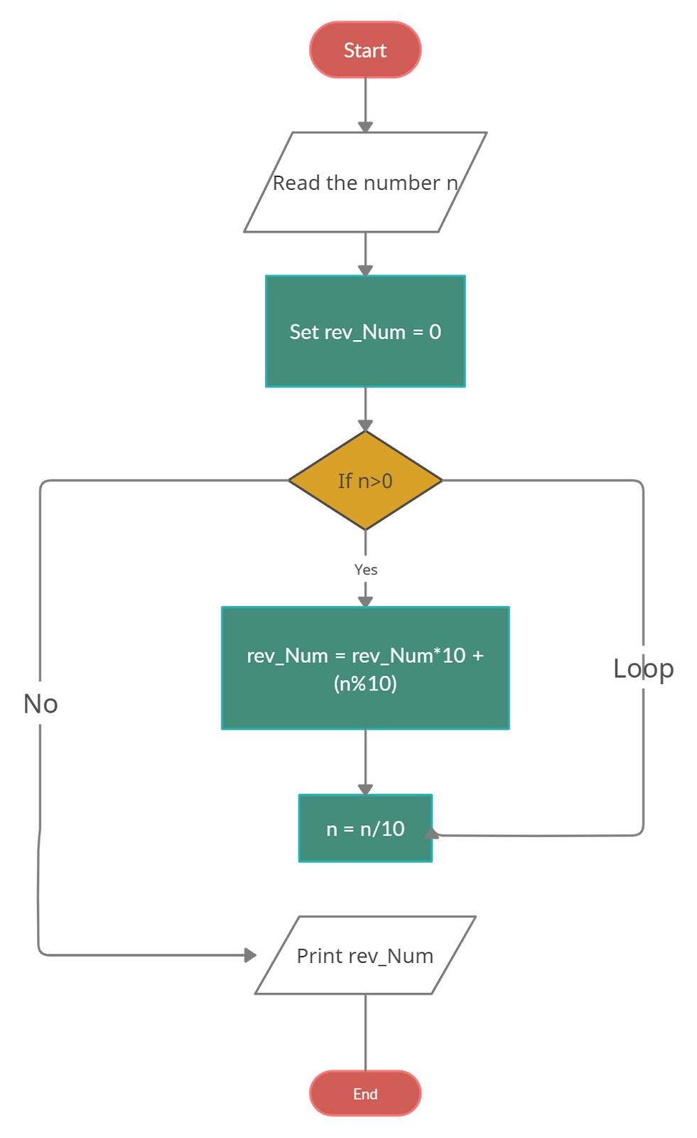
C Program To Reverse A Number Using Different Methods
What Is The Flowchart That Will Generate The Sum And Product Of 20 Numbers Quora
10 Flowchart Templates And Examples
10 Flowchart Templates And Examples
Flowchart Programming Project Flowchart Examples Sample Project Flowchart Flowchart Examples Flowchart Marketing Process Flowchart Examples Sample Project Flowchart
Next In R Flowchart Working And Examples Of Next In R

Exercise 1 Flowchart Dyclassroom Have Fun Learning

7 Types Of Flowcharts For Your Business Venngage
The Flowchart In The C Programming Language Javatpoint